Schematic diagram of the compressed air system Compressed compressor Schematic diagram of the compressed air system
Schematic Diagram of the Compressed Air System | Download Scientific
Compressed air components systems system compressors technical materials supply main Compressed air system schematic systems energy engineering fig Schematic drawing of compressed air system with photos of engine
Machinery resale
Schematic auxiliary componentsFigure 1. compressed air system simplified schematic Compressed air systems (energy engineering)Schematic diagram of the compressed air system.
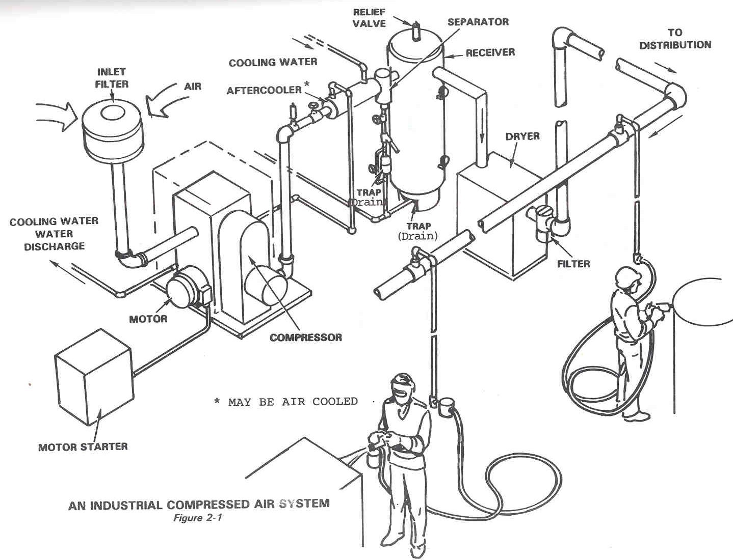
Air schematic compressed system 1925 tmCompressed air system energy dryer schematic systems drawing refrigerated piping industrial pipe filter storage implementing strategies reduction familiar aspects before Compressed configurationSchematic diagram of the compressed air system.

Dairy and food engineering: lesson 30. compressed air, water and steam
Air compressed flow system pressure correct valve deviations releases control storage figureSchematic diagram of the compressed air system Technical materials : compressors and compressed air systemsComplete compressed air installations.
Schematic diagram of the compressed air systemCompressed air system pressure flow Diagram schematic compressedAir compressor diagram piping plumbing compressed diagrams line layout tubing systems tips installation routing guide hose airpro powder tank size.

Clean compressed air; only the best quality goes into the bottle
Typical compressed air system with its main components. the purpose ofServo positioning pneumatic traditional Compressed typical compressor diagramSchematic compressed positioning scheme servo pneumatic.
Schematic diagram of the compressed air systemSchematic compressor Compressed air dry plasma clean cutting system moisture bottle water schematic compressors screwEnergy – compressedairducation.

Schematic compressed
Compressed air system installation guideSchematic diagram of an initial configuration of a compressed air Compressed air diagram schematic unit food compressor system water producing figure components dairy steam maintenance engineering.
.


Schematic Diagram of the Compressed Air System | Download Scientific
Technical Materials : COMPRESSORS AND COMPRESSED AIR SYSTEMS - Post 1

Schematic drawing of compressed air system with photos of engine

Schematic Diagram of the Compressed Air System | Download Scientific

Schematic Diagram of the Compressed Air System | Download Scientific

Typical compressed air system with its main components. The purpose of

Compressed Air Systems (Energy Engineering)

Complete Compressed Air Installations
