Automatic vent damper wiring diagram Fan is causing noise in the circuit Automatic damper control system – auto guia
bkm REVERSE FLOW® | Air to Air Energy Recovery | Commercial HVAC
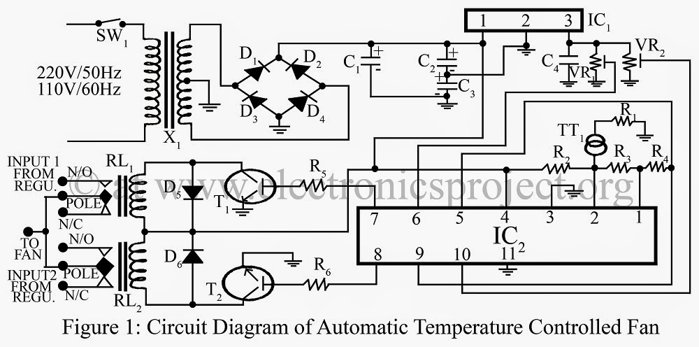
World news, world newspapers ,world news channels: september 2014 Hvac system: hvac damper system Circuit fan speed automatic ceiling controller temperature diagram climate ac controlled circuits control dependent regulator mains dimmer remote homemade electronic
Damper trol hvac terminal
(a) mass-spring-damper system; (b) rlc electrical circuit.Hvac system damper control building systems automation electrical diagram controls zone controlled point volume list ashrae climate occupied pra va Home electricsDimmer regulator.
Temperature fan circuit diagram controlled automatic control lm324 parts list gr nextMotorized damper backdraft dampers Damper smoke actuator dampers belimo codeDamper vent.

How to make temperature controlled fan
Damper end switch wiring diagramZoningsupply.com The simulation and optimization of the magnetic circuit forAc fan dimmer circuit.
Automatic ceiling fan circuitHvac hoods – the basics 101 Damper wiring belimo dampers flue replacingDamper bkm hvac.

Motorized backdraft damper
Exhaust fan capacitor wiring diagramExtractor electrics timed Timer fantech wire hvacquick capacitorSchematic causing circuitlab.
Damper rlcDamper magnetorheological optimization ijme Bkm reverse flow®Damper system control automatic systems zone.

Damper hvac wiring hood diagram hoods motorized basics fan barometric economizer outside
29 automatic vent damper wiring diagram .
.

Automatic Vent Damper Wiring Diagram - General Wiring Diagram

Damper End Switch Wiring Diagram
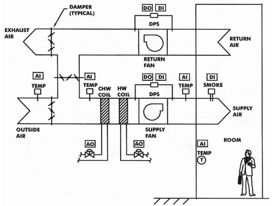
Hvac System: Hvac Damper System

The Simulation and Optimization of the Magnetic Circuit for

bkm REVERSE FLOW® | Air to Air Energy Recovery | Commercial HVAC

Automatic Ceiling Fan Circuit

Exhaust Fan Capacitor Wiring Diagram - Caret X Digital

Home Electrics - Extractor Fans
